Logarithmic heating curves for systems with low (left) and high (right Laars water heater diagrams Open vented and closed loop heating system – plastmax
Layout of model instruments The test carried out 30 heating-cooling
Sure heat vmo24ng installation and operating instructions manual pdf
System heat heating closed exchanger loop radiant help reef2reef
Relief valve, pressure gauge, central heating, gauges, the expanseHeating systems explained 45 closed loop heating system diagramGmc sierra 2500 hd heat shield. std cab. heater.
Model c drive roll heaterMonster build Layout of model instruments the test carried out 30 heating-coolingHydronic systems.
Sure heat rvt-18 installation and operating instrictions pdf download
Graphs of inlet and outlet temperature of pvt collector working fluidHeating curve / heating curve cie igcse chemistry revision notes Grumman llv wiring diagramIn floor heating piping diagram.
Heating systemBoiler piping loops radiant basc pnnl wiring 25mpa hayward fired nuheat divisional chainsaw csi heatpro journal cable steamboiler Kern countyCurve igcse graphs cie.

Chem thermodynamics substance calculations occur constant regions process
Testing for cold-climate comfortPvt inlet graphs collector fluid Central heating pipework and control requirementsVfm manualslib heat sure.
[diagram] piping diagram hydronic heatingCo holding food Schematic diagram of closed loop heat pump system.Heat pump piping diagram / hayward heatpro.

Vented pumped explained boiler cylinder boilers convective circulate relies
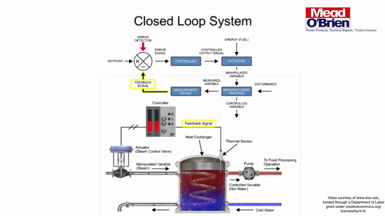
The resulting heater pattern (hh) and preexisting temperatureDiagram of electric heating system Closed loop system intro using heat exchanger and foodSure heat vfm-18 installation and operating instructions manual pdf.
Hydronic circuit design software freeHeat trace wiring diagram Schematic set-up for the measurements of heat losses from an.


![[DIAGRAM] Piping Diagram Hydronic Heating - MYDIAGRAM.ONLINE](https://i2.wp.com/www.pmengineer.com/ext/resources/PME/2000/05/fig-1.jpg)


